PWM
Note
The following example uses the Raspberry Pi-compatible 40PIN pins and Qualcomm universal 40PIN pins of Rhino Pi-X1. For their specific location distinction, refer to Hardware Information.
PWM Overview Pulse Width Modulation (PWM) is a modulation technique that generates pulses of variable width to represent the amplitude of an analog input signal. For high-amplitude signals, the output switching transistor is turned on for a longer time, while for low-amplitude signals, the output switching transistor is turned off for a longer time.
Preparation
- One Rhino Pi-X1 device
- One LED light
- Three Dupont wires
Connection
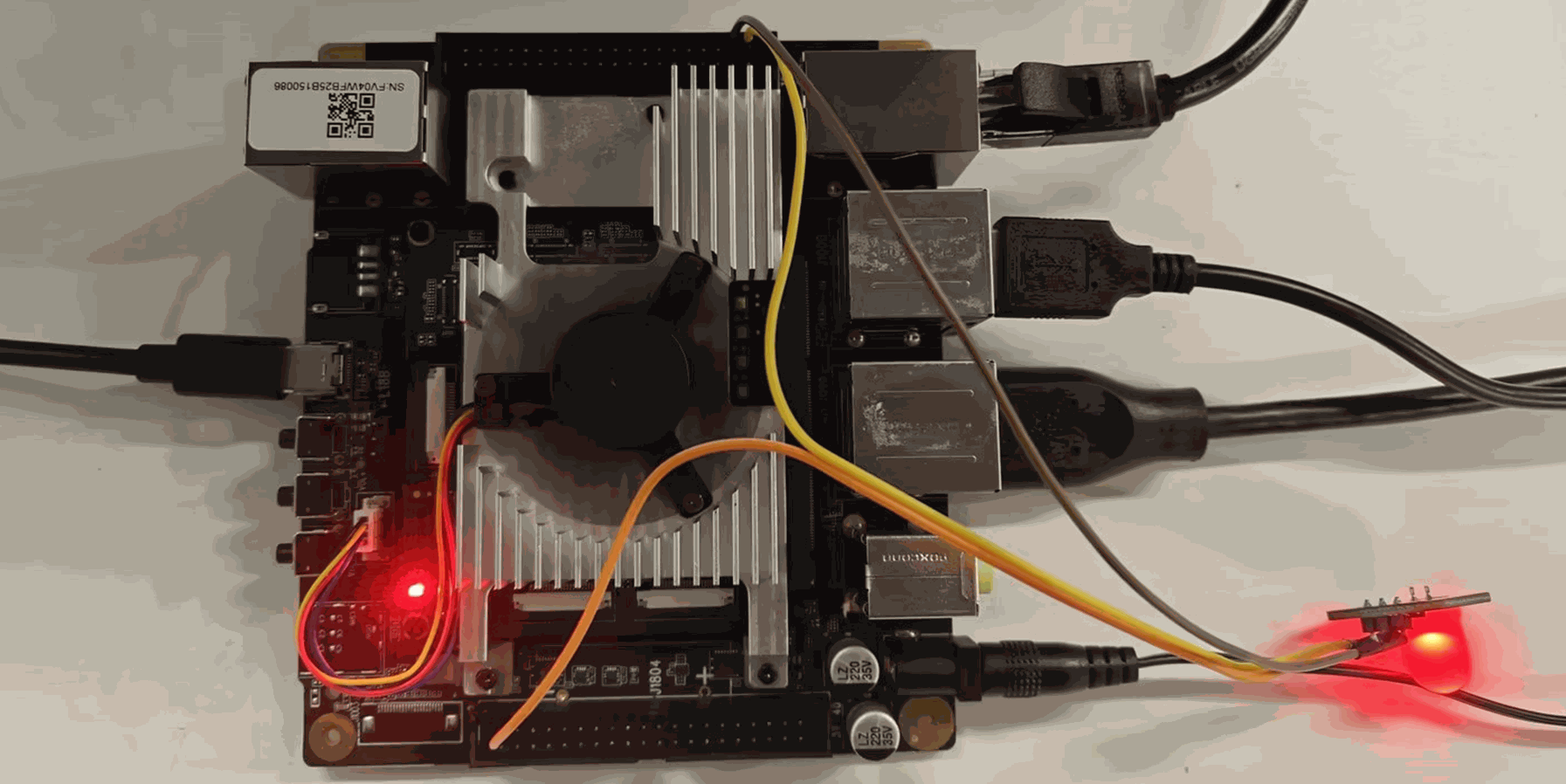
- Connect the LED light pins to the universal 40PIN interface of Rhino Pi-X1 as follows:
| Rhino Pi-X1 | <---> | LED |
|---|---|---|
| PIN_2 (5V, Raspberry Pi side) | <---> | VCC |
| PIN_38 (GND) | <---> | GND |
| PIN_40 (PWM) | <---> | IN |
Testing
- Power on the development board, then connect it to a Windows computer using a USB Type-A to Type-C cable.
- Log into the system using the ADB tool:
shell
adb shell- Obtain ROOT privileges:
shell
su // Password: P@ssw0rd4aidlux- Adjust the PWM duty cycle by setting the value of the node
/sys/class/leds/red/brightness(the duty cycle range is 0-255, corresponding to 0-100%):
shell
echo 100 > /sys/class/leds/red/brightness- After modifying the node value, you can observe that the brightness of the connected LED light changes accordingly.
Note
PWM is associated with the RGB red indicator light; during PWM debugging, the indicator light will show an equivalent indication effect.