GPIO
Note
The following example uses the Raspberry Pi-compatible 40PIN pins of Rhino Pi-X1. For their specific locations, refer to Hardware Information.
GPIO Overview General-Purpose Input/Output (GPIO) refers to non-dedicated digital signal pins on integrated circuits or electronic circuit boards (e.g., MCU/MPU). These pins can be configured as input, output, or both input and output, and are controllable via software.
Preparation
- One Rhino Pi-X1 device
- One LED light
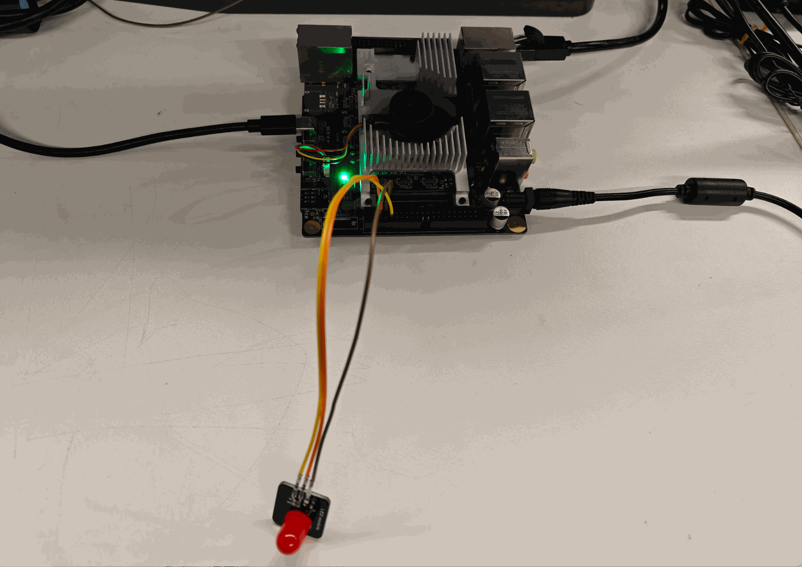
Connection
Taking the Raspberry Pi GPIO_00 interface as an example: Connect Rhino Pi-X1 to the LED light as shown in the figure. Connect the VCC, GND, and IN interfaces of the LED light to PIN_4 (VCC), PIN_6 (GND), and PIN_7 (GPIO_00) of Rhino Pi-X1 respectively.
Testing
Input Test Connect PIN7 to GND or 3.3V.
aidlux@aidlux:~$ sudo gpioget /dev/gpiochip0 0If connected to GND, the command outputs 0; if connected to 3.3V, it outputs 1.
Output Test
aidlux@aidlux:~$ sudo gpioset /dev/gpiochip0 0=1  # Output high level, LED turns on
aidlux@aidlux:~$ sudo gpioset /dev/gpiochip0 0=0  # Output low level, LED turns off
Note
Each GPIO can only be used by one process at a time; otherwise, a resource occupation error will be prompted.