I2C
Note
The following example uses the Raspberry Pi-compatible 40PIN pins of Rhino Pi-X1. For their specific locations, refer to Hardware Information.
I2C Overview I2C (Inter-Integrated Circuit; pronounced "eye-squared-see" or "eye-two-see"), also known as I2C or IIC, is a synchronous, multi-controller/multi-target (historically master/slave), single-ended, serial communication bus invented by Philips Semiconductors in 1982.
Preparation
- One Rhino Pi-X1 device
- One OLED display
Connection
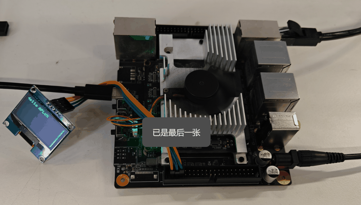
Connect Rhino Pi-X1 to the OLED display as follows:
| Rhino Pi-X1 | <--> | OLED |
|---|---|---|
| PIN_1 (VCC) | <--> | VCC |
| PIN_3 (SDA) | <--> | SDA |
| PIN_5 (SCL) | <--> | SCL |
| PIN_6 (GND) | <--> | GND |
Testing
- Open the terminal and install the required Python library with the following command:
sudo pip3 install python-peripheryConfirm the I2C channel and OLED address:
- I2C channel: 1 (i.e., /dev/i2c-1)
- OLED address: 0x3c
Create a new Python file named
i2c_test.pyand paste the following code into it:
from periphery import I2C
import time

I2C_ADDR = 0x3c
I2C_BUS = "/dev/i2c-1"

i2c = I2C(I2C_BUS)

# SSD1306 init_cmds
init_cmds = [
    0xAE,  # Display off
    0x00,  # Set lower column address
    0x10,  # Set higher column address
    0x40,  # Set display start line
    0xB0,  # Set page address
    0x81,  # Set contrast control
    0xCF,
    0xA1,  # Set segment remap
    0xA6,  # Normal display
    0xA8,  # Set multiplex ratio
    0x3F,
    0xC8,  # Set COM output scan direction
    0xD3,  # Set display offset
    0x00,
    0xD5,  # Set display clock divide ratio/oscillator frequency
    0x80,
    0xD9,  # Set pre-charge period
    0xF1,
    0xDA,  # Set COM pins hardware configuration
    0x12,
    0xDB,  # Set VCOMH deselect level
    0x40,
    0x8D,  # Enable charge pump regulator
    0x14,
    0xAF   # Display on
]

for cmd in init_cmds:
    i2c.transfer(I2C_ADDR, [I2C.Message([0x00, cmd])])

def oled_clear():
    for page in range(8):
        i2c.transfer(I2C_ADDR, [I2C.Message([0x00, 0xB0 + page])])
        i2c.transfer(I2C_ADDR, [I2C.Message([0x00, 0x00])])
        i2c.transfer(I2C_ADDR, [I2C.Message([0x00, 0x10])])
        for _ in range(128):
            i2c.transfer(I2C_ADDR, [I2C.Message([0x40, 0x00])])

char_map = {
    "H": [0x00, 0x7F, 0x08, 0x08, 0x08, 0x7F,],
    "R": [0x00, 0x7F, 0x09, 0x19, 0x29, 0x46],
    "e": [0x00, 0x38, 0x54, 0x54, 0x54, 0x18],
    "l": [0x00, 0x00, 0x41, 0x7F, 0x40, 0x00],
    "o": [0x00, 0x38, 0x44, 0x44, 0x44, 0x38],
    "A": [0x00, 0x7C, 0x12, 0x11, 0x12, 0x7C],
    "P": [0x00, 0x7F, 0x09, 0x09, 0x09, 0x06],
    "L": [0x00, 0x7F, 0x40, 0x40, 0x40, 0x40],
    "U": [0x00, 0x3E, 0x40, 0x40, 0x40, 0x3E],
    "X": [0x00, 0x63, 0x14, 0x08, 0x14, 0x63],
}

def string_to_bytes(string):
    bytes_list = []
    for char in string:
        bytes_list.extend(char_map.get(char, [0x00] * 4))
        bytes_list.append(0x00)
    return bytes_list

oled_clear()
hello_world_bytes = string_to_bytes("Hello APLUX")
i2c.transfer(I2C_ADDR, [I2C.Message([0x00, 0xB0])])
i2c.transfer(I2C_ADDR, [I2C.Message([0x00, 0x00])])
i2c.transfer(I2C_ADDR, [I2C.Message([0x00, 0x10])])
for byte in hello_world_bytes:
    i2c.transfer(I2C_ADDR, [I2C.Message([0x40, byte])])

i2c.close()- Run the script in the terminal with the following command:
sudo python3 i2c_test.pyAfter executing the above command, the OLED display will show the characters "Hello, APLUX".
Note
This test only demonstrates one set of I2C interfaces. Developers can use other I2C interfaces as needed, noting that the I2C channel will change accordingly.
| Group No. | I2C Interface | Remarks |
|---|---|---|
| 1 | PIN 3 (SDA) PIN 5 (SCL) | Built-in 10k pull-up resistor in level shift |
| 2 | PIN 13 (SDA) PIN 15 (SCL) | Built-in 10k pull-up resistor in level shift |
| 3 | PIN 27 (SDA) PIN 28 (SCL) | External 2.2k pull-up resistor |