Hardware Connection Guide
Hardware Connection Guide
Key Interface Pin Definitions
PCIe 16PIN Communication Interface (connected to Raspberry Pi)
| Pin Label | Signal Name | Level | Description |
|---|---|---|---|
| 1 | RESET | 3V3 | Compute card reset signal |
| 2 | CLK_REQ | 3V3 | PCIe clock request |
| 3 | WAKE | 3V3 | Wake signal |
| 4 | PWR_EN | 3V3 | Power enable |
| 5/8/11/14 | GND | - | Ground |
| 6/7 | PCIE_TX_N/PCIE_TX_P | - | PCIe TX differential pair |
| 9/10 | PCIE_RX_N/PCIE_RX_P | - | PCIe RX differential pair |
| 12/13 | PCIE_CLK_N/PCIE_CLK_P | - | PCIe clock differential pair |
| 15/16 | 5V | 5V | Power input |
Native 40PIN IO Interface (J2, connected to Raspberry Pi)
- Standard 2.54mm pitch 40PIN header, compatible with Raspberry Pi GPIO definitions
- Occupied pins:
- Pin 27 and 28: internally connected to E2PROM on the adapter board, unavailable for reuse
- Pin 33 and 35: internally connected to A8625 cooling fan control on the adapter board, unavailable for reuse
- Remaining pins are available for peripheral expansion. For full pin definitions, see Section 7.6 of the A8625 Compute Card Adapter Board Hardware Specification.
Other Key Interfaces
| Interface ID | Interface Name | Function |
|---|---|---|
| J10 | Type-C power input | 12V/3A input, powers the entire system |
| J3 | Type-C power output | 5V/3A output, powers Raspberry Pi 5 mainboard |
| J7 | Type-C debug interface | Breaks out A8625 UART debug serial for system log viewing |
| J5 | Type-C USB peripheral | Extends USB devices on A8625 compute card (for example USB drive, camera) |
| J6 | PWM fan header | Raspberry Pi outputs PWM signal to control A8625 cooling fan |
| J8 | PCIe to RJ45 | 2.5G Ethernet interface for communication with A8625 compute card |
Mechanical Connection and Cabling Steps
General notes: All connection operations must be done with power off. Discharge static electricity before operation to avoid damaging electronic components.
FPC cable usage notes:
Hold the connector when plugging/unplugging the FPC cable. Do not pull on the cable itself to avoid internal wire breakage.
Avoid excessive bending during installation. The bend radius should not be less than 5mm.
Make sure both ends are fully inserted and latched to prevent poor contact and communication interruptions.
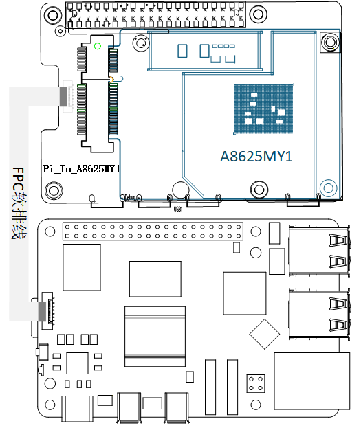
Stack-install the adapter board: Align and insert the 40PIN header of CEK2601-Pi5A8625MY1 into the 40PIN GPIO on Raspberry Pi 5. Insert the adapter board PCIe 16PIN connector into the Raspberry Pi PCIe slot and ensure good contact.
Install the A8625 compute card: Connect A8625MY1 to J8 on the adapter board via PCIe 16PIN interface, then secure the compute card and adapter board with screws.
Connect cooling fan: Connect the A8625 PWM fan to interface J6 on the adapter board.
Power connection: Connect a 12V/3A adapter to J10 on the adapter board, and connect J3 on the adapter board to the Raspberry Pi 5 power port with a Type-C cable.
Compute card communication connection (choose one, FPC cable recommended first):
- Recommended: PCIe FPC cable connection: Connect one end of the FPC cable to J8 on the adapter board (PCIe to RJ45) and the other end to the Ethernet port of A8625MY1. Compared with Ethernet cables, FPC cables provide more stable transmission and lower latency, effectively reducing packet loss during high-bandwidth AI data transfer.
- Recommended purchase link: https://item.taobao.com/item.htm?id=862597845004 (if unavailable, search for "Raspberry Pi 5 A8625 PCIe 2.5G FPC cable").
- Alternative: Gigabit Ethernet cable connection: Use a standard Gigabit Ethernet cable between J8 on the adapter board and the A8625 compute card Ethernet port, suitable for long-distance connection scenarios.
Debug and peripheral connection:
- Use a USB-A to USB-C cable to connect your PC to the J7 debug interface on the adapter board
- For USB peripheral expansion, connect devices to J5 on the adapter board